Atlas
-210, Atlas-210x, Atlas-215xModification and Information


![]() Updated with schematics and photos.
Updated with schematics and photos.
DOUBLE-SIDEBAND LIMITING RF SPEECH PROCESSOR
|
|
|
This simple
speech processor is suited for all Atlas 210-215 types. The audio signal from the first stage microphone amplifier Q202 (PC-200) is coupled to integrated oscillator and mixer circuit NE612A (SA612), which converts it to a 6.4 MHz signal. The heterodyning action of the mixer produces a double sideband signal (DSB), which is coupled to the second integrated clipper and mixer circuit. The DSB signal is then clipped in the TBA120A (SN76660) and is further converted back to audio for input to MIC. GAIN potentiometer. The resulting harmonics (of 6.4 MHz) are filtered out with simple RC filtering when it was demodulated back to audio. The result is a 'cleaner' clipped signal being finally transmitted. This increases the average output level of an audio signal from a microphone by clipping off the excessive signal peaks. By lowering the peaks in proportion to the average level, a higher average output level can be attained with an associated increase in intelligibility under difficult conditions. It is set up easily without special equipment because no RF filters are used. This effective design offers microphone level input and output adjustments. The clip level depends on the amount of microphone gain.The crystal of 6.4 MHz is not critical. Each other frequency of 3 - 10.7 MHz is useful because the internal oscillator start easily and there no RF filters. The oscillator can be omitted if there is another HF oscillator. A good result was reached by coupling the carrier oscillator signal (PC-600) from pin 6 and 7 of PC-300 to pin 6 of NE612A.
The modification is simple; nothing has to be changed on any of the original print boards. Just disconnect a wire on the top of potentiometer R5 (MIC. GAIN). That point easily can be spotted because resistor R6 is connected to it. The wire must soldered on the top of the potentiometer (P) at the input of the processor. The audio from the output of the processor is then coupled to the top of R5. That is all! Preferably use screened wire for the assembly to or from the processor. The clipping level can be adjusted with potentiometer P. Do not run the gain to far, or you will decrease the intelligibility of your audio. So the gain must be carefully adjusted. If you always use the same microphone, the adjustment can be done once.
Adjust R5 as follows: whistle in the microphone for maximum output of the transmitter, set P so that the voice peaks are just below the maximum level. Eventually check with a scoop if the voice peaks will not be reaching the maximum level.
It is possible to set the controls so that the peak envelope power reaches the desired level without activating the ALC at all.
The level then is only a few tenths of a dB below the level that would have been set by the ALC, but the transmission is a lot cleaner while maintaining very high average modulation.Probably the TBA120A or SN76660 are no longer manufactured, but it appears that they are offered still new (old stock).
VFO
My ATLAS
210 is successfully modified from 3.7 down to 3.5 MHz.|
|
|
(1) Remove the marked coil and replace with a coil of about 0.5 µH.
(2) Calibrate with the trimmer for "0 = 3.5 MHz" on the dial scale.
(3) Realign the 80m receiver input circuit for maximum sensitivity
.
17 m INSTEAD OF 10 m
VFO
My ATLAS 210x is successfully modified for the 17 m band by sacrifice the 10 m range. Output is 100 W.
|
|
|
|
Wafer A: Disconnect the wire to the 10m tap of L403 and solder a jumper to the 40 m contact. Wafer B: shortcut 1 × 4.7 pF cap. |
|
Adjust the 10 m (= 17 m) VFO trimmer C415 for an accurate dial calibration of 18.000 – 18.500 MHz. The VFO range is then moved up to 12.750 – 13.250 MHz.
RECEIVER INPUT TUNING
|
Eventually replace with 1 × ± 100 pF cap parallel to each coil. |
Testing the modified circuit using the soldering tags on top of the PCB. |
Final modification. |
Check for a coupling capacitor C813 of 4.7 pF and solder parallel to C814 and C 815 an capacitor of 56 pF, eventually 47 pF. Adjust the iron cores for maximum signal on ± 18.110 MHz.
I did not remove the PCB PC-800 but used the soldering tags for the final modification of the 10 m receiver input tuning transformer.
TRANSMITTER INPUT TUNING
|
|
|
|
Rewind 10 m toroids with 24 turns and a tap on 4 turns. |
|
Set the trimmers C921 and C922 for maximum output on ± 18.110 MHz.
LOW PASS FILTER
|
|
|
|
Using the 15 m low pass filter for 17 m (the 10 m LPF is disconnected). |
|
The low pass filter provides full coverage of the 17 m band and require no further adjustment.
MORE MODIFICATIONS
|
AGC & S-meter mods. |
PC-200A. |
|
PC-200A redrawn with sPlan.
PC-200C (the differences with PC-200A and PC-200B red are red coloured). |
|
|
AGC mods. |
PC-300C. |
|
Mixers PC-100A PC-100B PC-120B |
Mixers PC-200A PC-200B PC-200D |
|
|
|
PA bias
(G3YXM design) PC-500, PC-500D, PC-520.|
GPT transistor on top of Q506. Improved bias with an extra general purpose (GPT) transistor, for example 2N2905.
|
||||||||||||||||||||||||||||||||||
|
PC-900A and PC-900D. |
Note: the ATLAS RADIO INC. used CTC 2545, CTC A50-12 or CTC S70-12 transistors in the PC-500 amplifier!

Increase R516 (330 Ω) to ± 910 Ω for a correct indication of the collector current.
|
|
|
|
Eventually increase the output with an extra cap parallel to C505, but evenly decrease the output on 80 m and improves the overall stability of the amplifier with an one turn on T502 and feedback resistors to the collectors of Q504 and Q505. I was satisfied with C505 = 270 pF + 270 pF. The output of my PC-500D is not representative, may be you obtains more power on some bands.

For improved linearity and to prevent instability the output of my amplifier is limited with an extra feedback (fig») on transistor Q503. With a 1 kΩ pot and C270 I reduced the power to maximum 95 W.


|
12.5V 28 MHz |
Brand |
Class |
Pout |
Ic-max |
Gain (Gp) |
MD3 |
Replacement for: |
|
MRF453 |
Motorola |
HF communication |
60 W |
15 A |
13 dB |
– |
A50-12 CD2545 |
|
2SC2879 |
Toshiba |
AB |
100 W |
25 A |
13 dB |
-24 dB |
– |
|
2SC2290 |
Toshiba |
SSB |
60 W PEP |
20 A |
11.8 dB |
-30 dB |
– |
|
HF75-12 |
ASI |
AB |
75 W |
20 A |
13.5 dB |
-30 dB |
MRF454 SD1405 |
|
HF100-12 |
ASI |
C |
100 W |
20 A |
13 dB |
-30 dB |
– |
|
HF50-12F |
ASI |
C |
55 W |
12 A |
10 dB |
-30 dB |
– |
|
SD1446 |
SGS |
C |
70 W 50 MHz |
12 A |
10 dB |
? |
– |
|
NTE317 |
NTE |
HF communication |
70 W |
15 A |
13.5 dB |
? |
– |
EXPERIMENTS WITH OTHER TRANSISTORS
|
Test Q504, Q505 (2SC2879). |
Test Q503 (2SC1969).
Tested types. |
Test Q503 (2SC1306), Q504,Q505 (2SC2879). |
|
|
PC-500 with 2 × 2SC2879. |
|||
|
Rx/tx sensitivity PC-100A PC-100B |
|
Increased decoupling for improved sensitivity. |

PC-100A.
|
Termination mixers PC-100A PC-100B PC-200A PC-200B |
|
Termination of the mixers with non-inductive resistors. |
POST MIXER AMPLIFIER OR DIPLEXER?
PC-100A, PC-100B, PC-100D, PC-120B
|
|
|||
|
Amplifier with P8002.
Amplifier with J310. |
Termination of the 1st mixer with a diplexer.
|
||
|
|
|
||
|
Amplifier & gain control.
PC-100A redrawn with sPlan.
This modification with a J310 is suited for all PC-100 versions.
PC-100 updated with an extra gain control. |
|||
|
Microphone amp PC-200A PC-200B |
Increased MIC gain with an extra GPT transistor. |
|
|
|
(HF DSB) clipper Noise blanker PC-120B |
|
DSB clipper. |
Improved noise blanker. |
|
|
Circuits trimmed with this tool. |
|
Trimmer capacitors are located on PC-900A or PC-900B boards with the transmitter tuning input circuits. |
|
|
Carrier oscillator PC-600 |
|
|
IF crystal ladder filter (Oct. 1975). |
The normal carrier frequency is 5520 kHz and the opposite side band frequency is 5523.3 kHz.
|
|
Graph («fig) obtained by DJ9PK from his 8 pole ladder filter.
Graph on my analyzer. |


Removing black "paint" for improved screening and improved electrical contact for the (-) pole of the DC supply.


|
Home made 12 VDC connector |
|
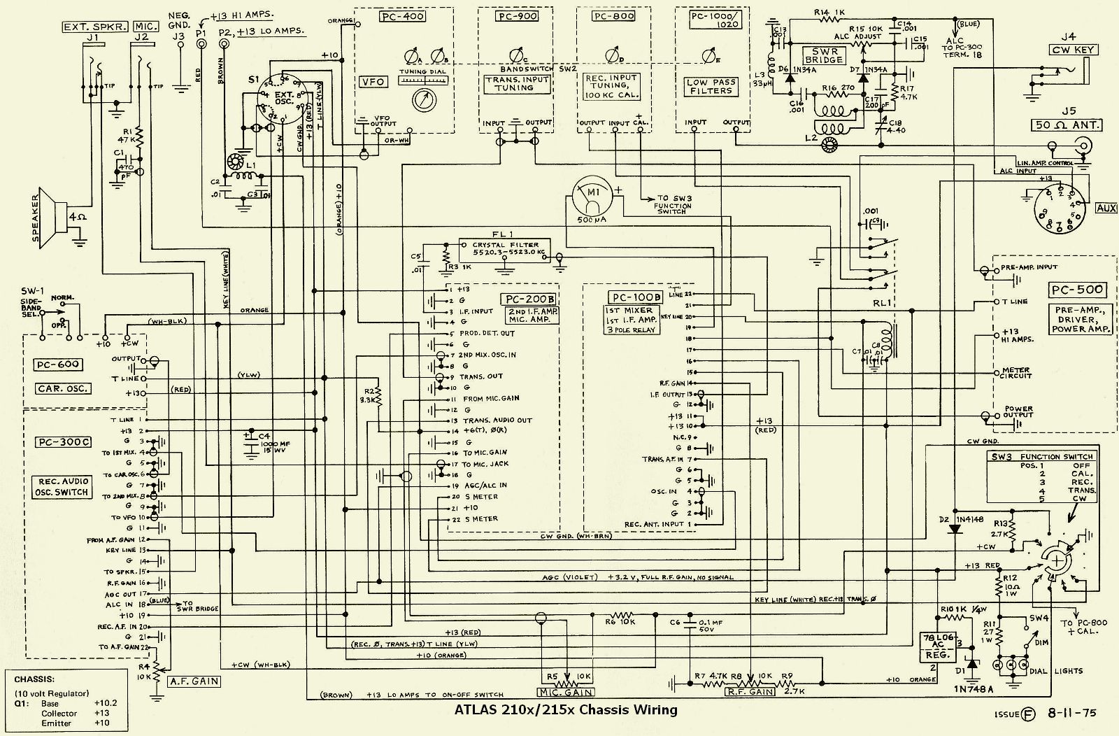
ATLAS 210x/215x Chassis Wiring (click to enlarge). |
|
Noise reduction of the regulator. |
|
![]()
![]()


 _
_